Translation and Segmentation
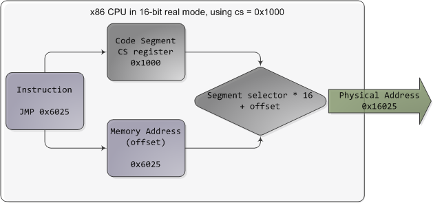
In the chipsets that power Intel motherboards, memory is accessed by the CPU via the front side bus, which connects it to the northbridge chip. The memory addresses exchanged in the front side bus are physical memory addresses, raw numbers from zero to the top of the available physical memory. These numbers are mapped to physical RAM sticks by the northbridge. Physical addresses are concrete and final – no translation, no paging, no privilege checks – you put them on the bus and that’s that. Within the CPU, however, programs use logical memory addresses, which must be translated into physical addresses before memory access can take place. Conceptually address translation looks like this:
![]()
This is not a physical diagram, only a depiction of the address translation process, specifically for when the CPU has paging enabled. If you turn off paging, the output from the segmentation unit is already a physical address; in 16-bit real mode that is always the case. Translation starts when the CPU executes an instruction that refers to a memory address. The first step is translating that logic address into a linear address. But why go through this step instead of having software use linear (or physical) addresses directly? For roughly the same reason humans have an appendix whose primary function is getting infected. It’s a wrinkle of evolution. To really make sense of x86 segmentation we need to go back to 1978.
The original 8086 had 16-bit registers and its instructions used mostly 8-bit or 16-bit operands. This allowed code to work with 216 bytes, or 64K of memory, yet Intel engineers were keen on letting the CPU use more memory without expanding the size of registers and instructions. So they introduced segment registers as a means to tell the CPU which 64K chunk of memory a program’s instructions were going to work on. It was a reasonable solution: first you load a segment register, effectively saying “here, I want to work on the memory chunk starting at X”; afterwards, 16-bit memory addresses used by your code are interpreted as offsets into your chunk, or segment. There were four segment registers: one for the stack (ss), one for program code (cs), and two for data (ds, es). Most programs were small enough back then to fit their whole stack, code, and data each in a 64K segment, so segmentation was often transparent.
Nowadays segmentation is still present and is always enabled in x86 processors. Each instruction that touches memory implicitly uses a segment register. For example, a jump instruction uses the code segment register (cs) whereas a stack push instruction uses the stack segment register (ss). In most cases you can explicitly override the segment register used by an instruction. Segment registers store 16-bit segment selectors; they can be loaded directly with instructions like MOV. The sole exception is cs, which can only be changed by instructions that affect the flow of execution, like CALL or JMP. Though segmentation is always on, it works differently in real mode versus protected mode.
In real mode, such as during early boot, the segment selector is a 16-bit number specifying the physical memory address for the start of a segment. This number must somehow be scaled, otherwise it would also be limited to 64K, defeating the purpose of segmentation. For example, the CPU could use the segment selector as the 16 most significant bits of the physical memory address (by shifting it 16 bits to the left, which is equivalent to multiplying by 216). This simple rule would enable segments to address 4 gigs of memory in 64K chunks, but it would increase chip packaging costs by requiring more physical address pins in the processor. So Intel made the decision to multiply the segment selector by only 24 (or 16), which in a single stroke confined memory to about 1MB and unduly complicated translation. Here’s an example showing a jump instruction where cs contains 0x1000:
Real mode segment starts range from 0 all the way to 0xFFFF0 (16 bytes short of 1 MB) in 16-byte increments. To these values you add a 16-bit offset (the logical address) between 0 and 0xFFFF. It follows that there are multiple segment/offset combinations pointing to the same memory location, and physical addresses fall above 1MB if your segment is high enough (see the infamous A20 line). Also, when writing C code in real mode a far pointer is a pointer that contains both the segment selector and the logical address, which allows it to address 1MB of memory. Far indeed. As programs started getting bigger and outgrowing 64K segments, segmentation and its strange ways complicated development for the x86 platform. This may all sound quaintly odd now but it has driven programmers into the wretched depths of madness.
In 32-bit protected mode, a segment selector is no longer a raw number, but instead it contains an index into a table of segment descriptors. The table is simply an array containing 8-byte records, where each record describes one segment and looks thus:
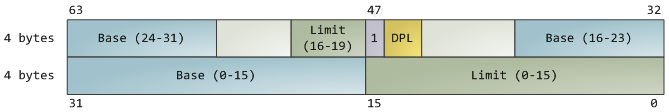 There are three types of segments: code, data, and system. For brevity, only the common features in the descriptor are shown here. The base address is a 32-bit linear address pointing to the beginning of the segment, while the limit specifies how big the segment is. Adding the base address to a logical memory address yields a linear address. DPL is the descriptor privilege level; it is a number from 0 (most privileged, kernel mode) to 3 (least privileged, user mode) that controls access to the segment.
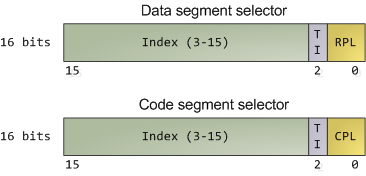
These segment descriptors are stored in two tables: the Global Descriptor Table (GDT) and the Local Descriptor Table (LDT). Each CPU (or core) in a computer contains a register called gdtr which stores the linear memory address of the first byte in the GDT. To choose a segment, you must load a segment register with a segment selector in the following format:
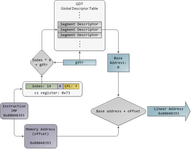
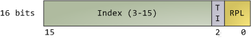 The TI bit is 0 for the GDT and 1 for the LDT, while the index specifies the desired segment selector within the table. We’ll deal with RPL, Requested Privilege Level, later on. Now, come to think of it, when the CPU is in 32-bit mode registers and instructions can address the entire linear address space anyway, so there’s really no need to give them a push with a base address or other shenanigan. So why not set the base address to zero and let logical addresses coincide with linear addresses? Intel docs call this “flat model” and it’s exactly what modern x86 kernels do (they use the basic flat model, specifically). Basic flat model is equivalent to disabling segmentation when it comes to translating memory addresses. So in all its glory, here’s the jump example running in 32-bit protected mode, with real-world values for a Linux user-mode app:
The contents of a segment descriptor are cached once they are accessed, so there’s no need to actually read the GDT in subsequent accesses, which would kill performance. Each segment register has a hidden part to store the cached descriptor that corresponds to its segment selector. For more details, including more info on the LDT, see chapter 3 of the Intel System Programming Guide Volume 3a. Volumes 2a and 2b, which cover every x86 instruction, also shed light on the various types of x86 addressing operands – 16-bit, 16-bit with segment selector (which can be used by far pointers), 32-bit, etc.
In Linux, only 3 segment descriptors are used during boot. They are defined with the GDT_ENTRY macro and stored in the boot_gdt array. Two of the segments are flat, addressing the entire 32-bit space: a code segment loaded into cs and a data segment loaded into the other segment registers. The third segment is a system segment called the Task State Segment. After boot, each CPU has its own copy of the GDT. They are all nearly identical, but a few entries change depending on the running process. You can see the layout of the Linux GDT in segment.h and its instantiation is here. There are four primary GDT entries: two flat ones for code and data in kernel mode, and another two for user mode. When looking at the Linux GDT, notice the holes inserted on purpose to align data with CPU cache lines – an artifact of the von Neumann bottleneck that has become a plague.
Finally, the classic “Segmentation fault” Unix error message is not due to x86-style segments, but rather invalid memory addresses normally detected by the paging unit – alas, topic for an upcoming post.
Intel deftly worked around their original segmentation kludge, offering a flexible way for us to choose whether to segment or go flat. Since coinciding logical and linear addresses are simpler to handle, they became standard, such that 64-bit mode now enforces a flat linear address space. But even in flat mode segments are still crucial for x86 protection, the mechanism that defends the kernel from user-mode processes and every process from each other. It’s a dog eat dog world out there! In the next post, we’ll take a peek at protection levels and how segments implement them.
CPU Rings, Privilege, and Protection
You probably know intuitively that applications have limited powers in Intel x86 computers and that only operating system code can perform certain tasks, but do you know how this really works? This post takes a look at x86 privilege levels, the mechanism whereby the OS and CPU conspire to restrict what user-mode programs can do. There are four privilege levels, numbered 0 (most privileged) to 3 (least privileged), and three main resources being protected: memory, I/O ports, and the ability to execute certain machine instructions. At any given time, an x86 CPU is running in a specific privilege level, which determines what code can and cannot do. These privilege levels are often described as protection rings, with the innermost ring corresponding to highest privilege. Most modern x86 kernels use only two privilege levels, 0 and 3:

About 15 machine instructions, out of dozens, are restricted by the CPU to ring zero. Many others have limitations on their operands. These instructions can subvert the protection mechanism or otherwise foment chaos if allowed in user mode, so they are reserved to the kernel. An attempt to run them outside of ring zero causes a general-protection exception, like when a program uses invalid memory addresses. Likewise, access to memory and I/O ports is restricted based on privilege level. But before we look at protection mechanisms, let’s see exactly how the CPU keeps track of the current privilege level, which involves the segment selectors from the previous post. Here they are:
The full contents of data segment selectors are loaded directly by code into various segment registers such as ss (stack segment register) and ds (data segment register). This includes the contents of the Requested Privilege Level (RPL) field, whose meaning we tackle in a bit. The code segment register (cs) is, however, magical. First, its contents cannot be set directly by load instructions such as mov, but rather only by instructions that alter the flow of program execution, like call. Second, and importantly for us, instead of an RPL field that can be set by code, cs has a Current Privilege Level (CPL) field maintained by the CPU itself. This 2-bit CPL field in the code segment register is always equal to the CPU’s current privilege level. The Intel docs wobble a little on this fact, and sometimes online documents confuse the issue, but that’s the hard and fast rule. At any time, no matter what’s going on in the CPU, a look at the CPL in cs will tell you the privilege level code is running with.
Keep in mind that the CPU privilege level has nothing to do with operating system users. Whether you’re root, Administrator, guest, or a regular user, it does not matter. All user code runs in ring 3 and all kernel code runs in ring 0, regardless of the OS user on whose behalf the code operates. Sometimes certain kernel tasks can be pushed to user mode, for example user-mode device drivers in Windows Vista, but these are just special processes doing a job for the kernel and can usually be killed without major consequences.
Due to restricted access to memory and I/O ports, user mode can do almost nothing to the outside world without calling on the kernel. It can’t open files, send network packets, print to the screen, or allocate memory. User processes run in a severely limited sandbox set up by the gods of ring zero. That’s why it’s impossible, by design, for a process to leak memory beyond its existence or leave open files after it exits. All of the data structures that control such things – memory, open files, etc – cannot be touched directly by user code; once a process finishes, the sandbox is torn down by the kernel. That’s why our servers can have 600 days of uptime – as long as the hardware and the kernel don’t crap out, stuff can run for ever. This is also why Windows 95 / 98 crashed so much: it’s not because “M$ sucks” but because important data structures were left accessible to user mode for compatibility reasons. It was probably a good trade-off at the time, albeit at high cost.
The CPU protects memory at two crucial points: when a segment selector is loaded and when a page of memory is accessed with a linear address. Protection thus mirrors memory address translation where both segmentation and paging are involved. When a data segment selector is being loaded, the check below takes place:

Since a higher number means less privilege, MAX() above picks the least privileged of CPL and RPL, and compares it to the descriptor privilege level (DPL). If the DPL is higher or equal, then access is allowed. The idea behind RPL is to allow kernel code to load a segment using lowered privilege. For example, you could use an RPL of 3 to ensure that a given operation uses segments accessible to user-mode. The exception is for the stack segment register ss, for which the three of CPL, RPL, and DPL must match exactly.
In truth, segment protection scarcely matters because modern kernels use a flat address space where the user-mode segments can reach the entire linear address space. Useful memory protection is done in the paging unit when a linear address is converted into a physical address. Each memory page is a block of bytes described by a page table entry containing two fields related to protection: a supervisor flag and a read/write flag. The supervisor flag is the primary x86 memory protection mechanism used by kernels. When it is on, the page cannot be accessed from ring 3. While the read/write flag isn’t as important for enforcing privilege, it’s still useful. When a process is loaded, pages storing binary images (code) are marked as read only, thereby catching some pointer errors if a program attempts to write to these pages. This flag is also used to implement copy on write when a process is forked in Unix. Upon forking, the parent’s pages are marked read only and shared with the forked child. If either process attempts to write to the page, the processor triggers a fault and the kernel knows to duplicate the page and mark it read/write for the writing process.
Finally, we need a way for the CPU to switch between privilege levels. If ring 3 code could transfer control to arbitrary spots in the kernel, it would be easy to subvert the operating system by jumping into the wrong (right?) places. A controlled transfer is necessary. This is accomplished via gate descriptors and via the sysenter instruction. A gate descriptor is a segment descriptor of type system, and comes in four sub-types: call-gate descriptor, interrupt-gate descriptor, trap-gate descriptor, and task-gate descriptor. Call gates provide a kernel entry point that can be used with ordinary call and jmp instructions, but they aren’t used much so I’ll ignore them. Task gates aren’t so hot either (in Linux, they are only used in double faults, which are caused by either kernel or hardware problems).
That leaves two juicier ones: interrupt and trap gates, which are used to handle hardware interrupts (e.g., keyboard, timer, disks) and exceptions (e.g., page faults, divide by zero). I’ll refer to both as an “interrupt”. These gate descriptors are stored in the Interrupt Descriptor Table (IDT). Each interrupt is assigned a number between 0 and 255 called a vector, which the processor uses as an index into the IDT when figuring out which gate descriptor to use when handling the interrupt. Interrupt and trap gates are nearly identical. Their format is shown below along with the privilege checks enforced when an interrupt happens. I filled in some values for the Linux kernel to make things concrete.
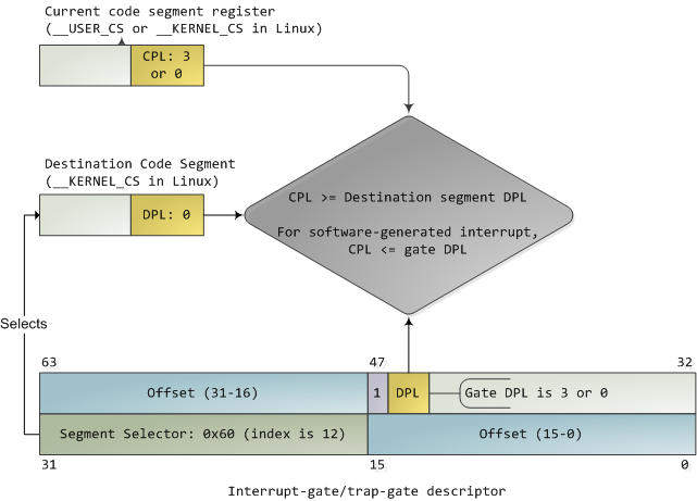
Both the DPL and the segment selector in the gate regulate access, while segment selector plus offset together nail down an entry point for the interrupt handler code. Kernels normally use the segment selector for the kernel code segment in these gate descriptors. An interrupt can never transfer control from a more-privileged to a less-privileged ring. Privilege must either stay the same (when the kernel itself is interrupted) or be elevated (when user-mode code is interrupted). In either case, the resulting CPL will be equal to to the DPL of the destination code segment; if the CPL changes, a stack switch also occurs. If an interrupt is triggered by code via an instruction like int n, one more check takes place: the gate DPL must be at the same or lower privilege as the CPL. This prevents user code from triggering random interrupts. If these checks fail – you guessed it – a general-protection exception happens. All Linux interrupt handlers end up running in ring zero.
During initialization, the Linux kernel first sets up an IDT in setup_idt() that ignores all interrupts. It then uses functions in include/asm-x86/desc.h to flesh out common IDT entries in arch/x86/kernel/traps_32.c. In Linux, a gate descriptor with “system” in its name is accessible from user mode and its set function uses a DPL of 3. A “system gate” is an Intel trap gate accessible to user mode. Otherwise, the terminology matches up. Hardware interrupt gates are not set here however, but instead in the appropriate drivers.
Three gates are accessible to user mode: vectors 3 and 4 are used for debugging and checking for numeric overflows, respectively. Then a system gate is set up for the SYSCALL_VECTOR, which is 0x80 for the x86 architecture. This was the mechanism for a process to transfer control to the kernel, to make a system call, and back in the day I applied for an “int 0x80” vanity license plate :).
Starting with the Pentium Pro, the sysenter instruction was introduced as a faster way to make system calls. It relies on special-purpose CPU registers that store the code segment, entry point, and other tidbits for the kernel system call handler. When sysenter is executed the CPU does no privilege checking, going immediately into CPL 0 and loading new values into the registers for code and stack (cs, eip, ss, and esp). Only ring zero can load the sysenter setup registers, which is done in enable_sep_cpu().
Finally, when it’s time to return to ring 3, the kernel issues an iret or sysexit instruction to return from interrupts and system calls, respectively, thus leaving ring 0 and resuming execution of user code with a CPL of 3.